

Isolation and Conversion of Standard Signals
Isolation Amplifier DN 2400
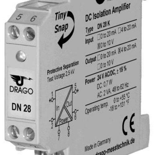
Input: 0…20 mA, 4…20 mA, 0…10 V
Output: 0…20 mA, 4…20 mA, 0…10 V
Power supply: 20 … 253 V AC/DC
Features: Pluggable screw clamp terminals, calibrated signal setting,
housing width: 12.5 mm
Technical Data
Input
Input signal 1) 0…20 mA, 4…20 mA, 0…10 V
terminal/switch selectable
Input resistance Current input
Voltage input approx. 22 Ohm
approx. 1 MOhm
Overload Current input
Voltage input ≤ 200 mA
Voltage limitation via 30 V Z-Diode, max. continuous current 30 mA
Output
Output signal 0…20 mA, 4…20 mA, 0…10 V, umschaltbar
Load Current output
Voltage output ≤ 10 V (500 Ohm at 20 mA)
≤ 10 mA (1 kOhm at 10 V)
Offset 20 µA / 10 mV
Ripple < 20 mVrms
General Data
Transmission error 0.3 % of measured value
Temperature coefficient 2) 150 ppm/K of final value
Cut-off frequency (-3 dB) 1 kHz
Test voltage 2.5 kV, 50 Hz
Input against output against power supply
Working voltage 3)
(Basic Insulation) Up to 600 V AC/DC for overvoltage category II and pollution degree 2 acc. to EN 61010-1 between all circuits.
Ambient temperature Operation
Transport and storage –10 °C to +60 °C
–20 °C to +80 °C
Power supply 20 … 253 V AC/DC, AC 48 … 62 Hz, approx. 3 VA
DC approx. 1.5 W
EMC 4) EMVG, EN 61326 -1
Construction 12.5 mm housing, protection type: IP 20
Weight Approx. 100 g
Factory setting
Average TC in specified operating temperature range
As far as practicable the standards and rules mentioned above are considered by development and production of our devices. In addition the assembly rules for our devices are to be considered by installation in other equipments. For applications with high working voltages, take measures to prevent accidental contact and make sure that there is sufficient distance or insulation between adjacent situated devices.
Minor deviations possible during interference
Bold: Factory setting for DN 2400 AG